Overview
The Honeywell ControlEdge HC900 Controller is an advanced loop and logic controller offering a modular designsized to satisfy the control and data acquisition needs of a wide range of process equipment
I/O Modules The following I/O modules are available to create a custom control solution.
• 16 Channel Universal IO Module Galavanically isolated Input/Output to chassis (p.29)
• 8-point universal analog input modules: Galvanic isolation point to chassis inputs may be mixed on a module and may include multiple thermocouple types, RTDs, ohms, voltage or mill voltage types – all easily assigned using the Process Control Designer configuration tool. High point-to-point galvanic isolation simplifies installation and saves the expense of external isolation hardware (p.8).
• 16-point high level analog input module: each point is configurable for V or mA. Galvanically isolated point to chassis. Galvanically isolated point to point (p.12). 250- ohm shunt resistors can be added per channel.
• 4-point galvanically isolated analog output module. Galvanically isolated point to chassis supports from 0 to 20mA each (p.14).
• 8-point analog output, galvanically isolated in 2 groups of 4 points. Galvanically isolated point to chassis. Supports from 0 to 20mA each (p.15).
• 16-point analog output, galvanically isolated in 4 groups of 4 points. Galvanically isolated point to chassis. Supports from 0 to 20mA each (p.16).
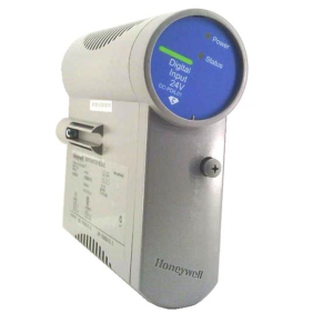
• 16-point digital input modules: Contact closure type, DC Voltage, AC Voltage and AC/DC voltage types (p.17). Galvanically isolated in groups of 8 channel to chassis
• 32-point digital input module: DC voltage. Galvanically isolated point to chassis. Galvanically isolated in 2 groups of 16 points (p.2117).
• 8-point AC or 16-point DC digital output modules (sinking type). Galvanically isolated point to chassis. Galvanically isolated in 2 groups of 8 points (p.20).
Specifications for modules
I/O Module Attributes
Remove & Insert under power Standard. Modules are automatically sensed and configured on insertion. Field power
shall be disconnected before removing field terminal blocks.
LED Channel State indicators Via light pipes at front of module, one state LED for each digital I/O point – green
indicates ON, logic side
LED Module Status indicator Via light pipe, one per module, tri-color to represent module status, Green = OK, Red
= Fault (# of flashes indicates fault), Amber = Override (Force)
I/O Labels Color-coded, on module door, removable, with write-on area to label I/O
Processor Micro-controller per module for parallel processing
Terminal Boards 20 screw: Barrier or Euro style, tin-plated or gold-plated (for DC connections)
36 screw: Euro style gold plated (Required with certain higher capacity modules)
Keying Hardware keying matches each module to its terminal block with its field wiring.
Environmental and Vibration Specifications
Mounting
Standard 35mm wide DIN Rail Provides connection of field wiring to controller I/O within an enclosure only.
Dimensions 4.38” (111.1 mm) x 3.70” (94.0mm) x 2.60” (66.0mm) (L x W x H)
Vibration
Amplitude
Acceleration
Vibration
5Hz to 15.77Hz, 2.03mm (0.08”) amplitude (peak to peak)
15.77 to 250Hz, 1.0-g
Sweeping, at rate of .33 octave/min.
Tray material
Tray and end caps
Flammability
Polyvinyl Chloride (PVC)
UL94-V0
Environmental
Temperature
Relative Humidity
Harsh Environment **
ROHS**
** Except PSU module
Operating: 0 deg. C (32F) to 60 deg. C (140F)
Storage: -40 deg. C (140F) to 70 deg. C (158F)
Operating: 10% to 90% Non-condensing
Storage: 5% to 95% Non-condensing
All the modules including CPU, Scanner, RTP, Backplane, RSM/PSM, and
Backplanes have conformal coating that is suitable for operation in G3 level of harsh
environment. Power Supply Units (PSU) do not have conformal coating.
Entire system is compliant to RoHS 2 directive, except PSU.